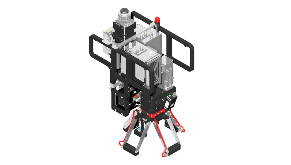
RLW-S | Reliable welding for difficult applications
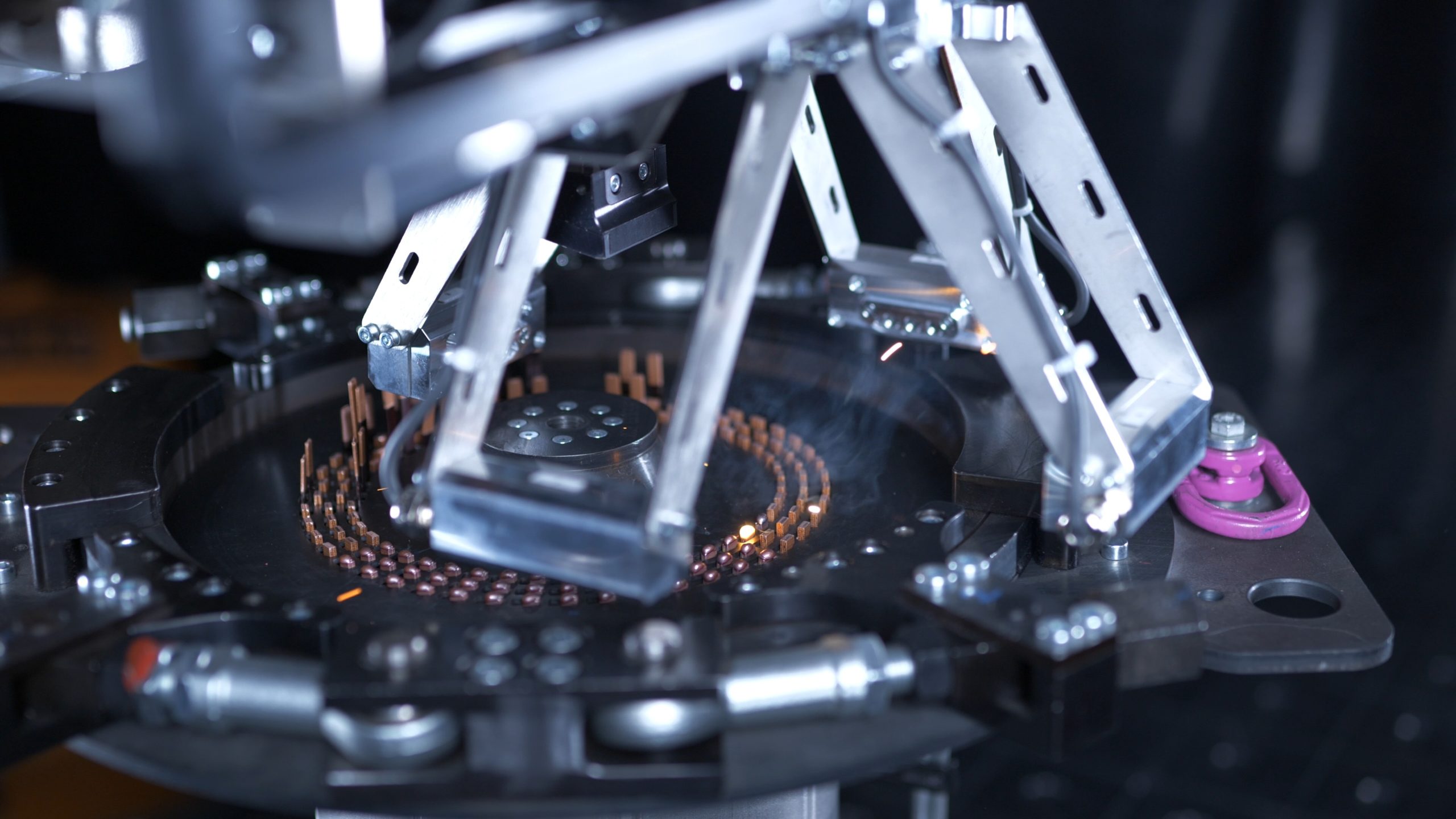
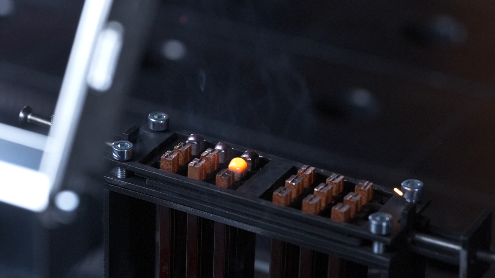
The RLW-S is ideal for the demanding task of welding of copper hairpins. This is made possible in part by the integrated camera sensor coaxially positioned to the laser beam. The sensor identifies the processing point even with different levels of reflectivity on the hairpin surfaces. It also ensures continuous process monitoring for high process reliability. This gives customers maximum dependability with strong, pore-free seams at high reproduction rates.
Function description
The RLW-S enables automatic recognition of patterns on the component as well as the position of the laser beam relative to the pattern contour. This makes it possible to define specific welding paths. A camera positioned coaxially to the laser beam detects the pattern layer(s). The movement of the laser beam is then calculated and executed via the path planning according to the parameterization. The deflection of the laser beam takes place via highly dynamic scanner axes and allows a positioning on the component along with a manipulation of the heat input via oscillation movements.
Areas of application
- Laser welding for e-mobility
- Automatic detection and welding of geometry patterns based on a gray image evaluation, for example for hairpins on electric motors or radiator tubes on EGR coolers
- Adaptation and optimization of image recognition possible for each application
Advantages
- Optimization of image recognition according to component requirements for reliable detection of hairpins, etc.
- Separated bright and dark-field illumination modules, which are individually controllable to obtain a most optimal brightness of the part
- Integrated 3-line-triangulation-projector to determine the height of each pin in the camera field
- Adapted process strategy and optical conditions for low-spatter copper welding
- SCanSeam: Special welding strategy for contacting busbars
- In planning: complete process monitoring for optimal process reliability
Properties
- Each position in the field is based on Cartesian coordinates, no field distortion at high deflection levels
- Precise laser spot and sensor position across the entire scan field in the overlay
- Automatic pattern recognition and calculation of the welding strategy
- Consideration of application-specific process requirements (e.g. coupling onto copper, etc.)
- Graphical parameterization of samples via separate parameterization software (GUI)
- Synchronized and highly dynamic positioning reaction by the scanner up to 1000Hz
- Modular design based on Scansonic scapacs® system, practically limitless adaptation of optical properties, fiber couplings, fieldbus interfaces, etc.
Supported Laser
- Fibre laser
- Disk laser
Further product information
- Fiber couplings for the following types of fiber optic cables: Trumpf-B, Trumpf-D, Optoskand QBH
- Fieldbus types: Profibus, Interbus, Profinet, Devicenet, Ethernet/IP
- Interface laser power: various current and voltage interface
- Optical ratio 1:2
Options
- In progress: SCeye quality estimations and process logging
- Monitoring of safety glass
- Velve terminal for cross-jets and cone jets
- Amount and position of bright and dark-field illumination modules can be selected
| Power supply | 400 V / 32 A (extern), 24 V / 55 A (intern) |
| Weight | approx. 25 kg (depending on configuration) |
| Operating wavelength | 1030 ... 1080 nm (disc laser to fibre laser) |
| Permissible laser power | max. 8 kW |
| Total angle of divergence Φ; BPP | Φ = 250 mrad (99 % of power capacity); BPP ≤ 25 mm∙mrad |
| Current magnification factor | 1:2.4 or 1:1.7 |
| Field size (for F400) | X = 38 mm / Y = 56 mm |
| Available focal length | 400 mm or f = 300 mm |
| IP protection degree | 64 (when the laser light cable is connected) |
| Laser protection class | 4 |
Contact us
Service
Technical Service
phone +49 - 30 - 91 20 74-311
Mon - Sun 8 a.m. - 4 p.m. (Sat/Sun for emergencies)
fax +49 - 30 - 91 20 74-333
e-mail service@scansonic.de


